Read the stories from our teams, as they progressed through each of their own projects. Each story will be listed below in chronological order of its arrival.
ANNOUNCEMENT
COVID-19 UPDATE: Due to the COVID-19 virus outbreak, our teams have not been able to complete their projects since June 2020, and as such – their information is not yet available. We will provide this information once the teams are back into building their telescopes and have outlined their journey / results.
To keep up to date of when this happens, and the latest information about this project – please follow our project on our @SpaceAusDotCom Twitter or Instagram, under the hashtag #SpaceAusScope.
Date: 15 January 2021
Team: Kent Rogers
Project Stage: Completed
The following post has been supplied by Kent Rogers from Melbourne and has been replicated with permissions. All images have been supplied by Mr Rogers and approved for usage.
A Wheelie Bin Radio Telescope!
by Kent Rogers
Having a passing interest in astronomy and particularly radio astronomy, I had long held the ambition of constructing my own backyard radio telescope. For many decades, this seemed a task requiring a level of commitment beyond what I was willing or able to devote. In 2020, finding myself recently retired and looking for a project during Covid 19 lockdown, I again looked at the possibility of undertaking this task. A search of the internet revealed a number of articles about building backyard radio telescopes. What’s more advances in microelectronics over the last ten or more years meant that the required preamps, filters and LNAs were now easily available in ready built affordable packages.
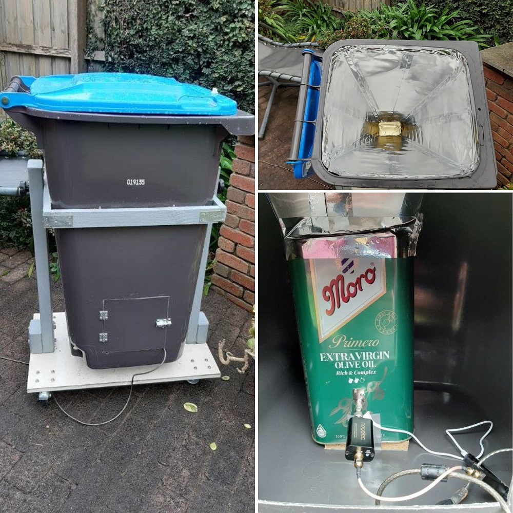
A number of articles [1,2,3,4] caught my attention regarding construction of small horn antennas that seemed relatively easy to construct and held the exciting prospect of being able to detect neutral atomic hydrogen (H1) line radio emissions from the Milky Way. It was one of these backyard radio telescopes that I decided to build. Similar to telescopes described in a number of articles, the scope that I constructed is designed to detect H1 emissions at 21 centimetre wavelengths. The main addition to my telescope is to make it weatherproof by housing it within a 240 litre wheelie bin. The size of a 240 litre wheelie bin enabled all of the horn, waveguide and electronic components to be housed within it with only minimal compromise on the size of the horn and hence gain of the antenna. The size of the bin allowed the horn throat to be 560mm x 510mm with a height of 640mm to the top of the olive oil can waveguide. This resulted in a calculated gain of 17.5dB and a 3dB beamwidth of approximately 27°.
The antenna components are therefore:
- 240 litre wheelie bin
- Horn made from aluminium flashing (0.7mm thick) and tape
- Waveguide made from a 4 litre olive oil tin
- Antenna made from straightened paperclip soldered to a TV PAL socket
- PAL to F and F to SMA adaptors
- Nooelec SAWbird+ H1 – Premium SAW Filter & LNA for H1 Line (21cm) applications.
- Nooelec NESDR Smart v4 SDR Premium
- 20 metre USB data cable with inbuilt signal amplifier
- PC running Windows 10
- SDRSharp v 1.0.0.1732 RTL-SDR (USB) software with IF Average plug in
- Stellarium 0.20.2 software
Timber was securely taped to the bottom of the waveguide olive oil tin which then was attached to the base of the wheelie bin by 4 small bolts and the four sides of the horn taped together with flashing tape and taped to both the waveguide and top rim of the wheelie bin. The paper clip antenna was cut to 5.25cm (quarter wavelength) and secured via the socket attached through the wall of the waveguide. The antenna is located 6.75cm from the back wall of the waveguide. This is a quarter of the modified wavelength within the waveguide and is determined by the dimensions of the waveguide. In this case, the waveguide opening of 16.8cm x 10.4cm results in a working wavelength range of 33.66cm to 20.8cm i.e. a bandwidth of 1,114 MHz to 1,693 MHz. The free space hydrogen line wavelength of 21cm is modified to 27cm within this waveguide.
An access hatch with a hinged door was cut in the side of the wheelie bin to enable access to the electronics at its base. A 20m USB cable was run through a slot in the hatch door then under the house to a PC located indoors. I also constructed an altazimuth mount for the telescope. This was a timber construction consisting of a rectangular frame mounted on posts attached to a timber platform with castors (a moving dolly). This enabled the telescope to be rotated both vertically and horizontally.
The biggest challenge was setting up the required SDR software on the PC. I tried both HDSDR and SDRSharp and found that SDRSharp was the preferred software once the IF Average plugin was downloaded and installed. This plugin enabled the signal to be averaged over 902,000 samples which successfully extracted the H1 signal from background noise. An online article in RTL-SDR.COM [5] described this software set up as well as running the star map software, Stellarium, at the same time as SDRSharp. Doing this enabled me to locate the Milky Way in relation to the antenna direction even during daylight. Using the galactic grid of Stellarium also meant that it was possible to identify the direction of the signal origin when the Milky Way was in view.
Even though I built an altazimuth mount for my wheelie bin telescope, I initially pointed the telescope straight up at the azimuth and took regular recordings as the Milky Way drifted in and out of range. On first light, I was delighted and amazed to receive strong signals each time the Milky Way drifted into view.
A sequence of fourteen captures was taken from Melbourne, Australia on 31 July 2020 and 1 August 2020 showing the rise and fall of the hydrogen line signal with the telescope pointing at the azimuth. Five of these captures are shown below to illustrate the change in signal as the Milky Way drifts across the field of view.
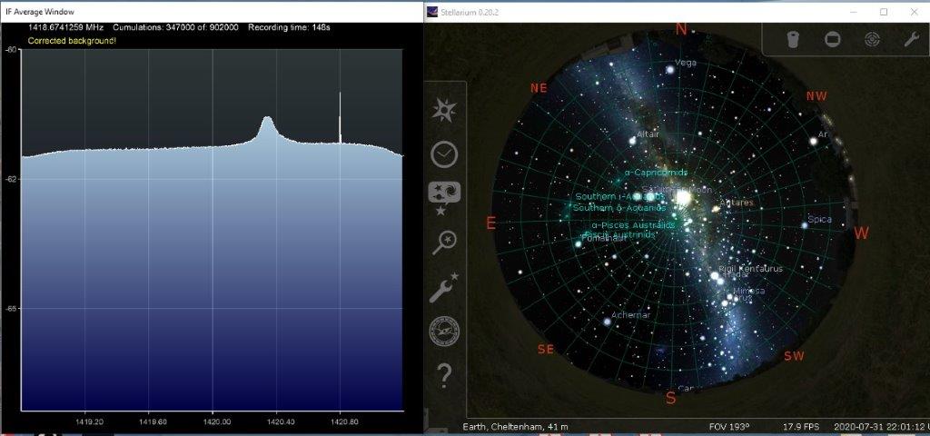

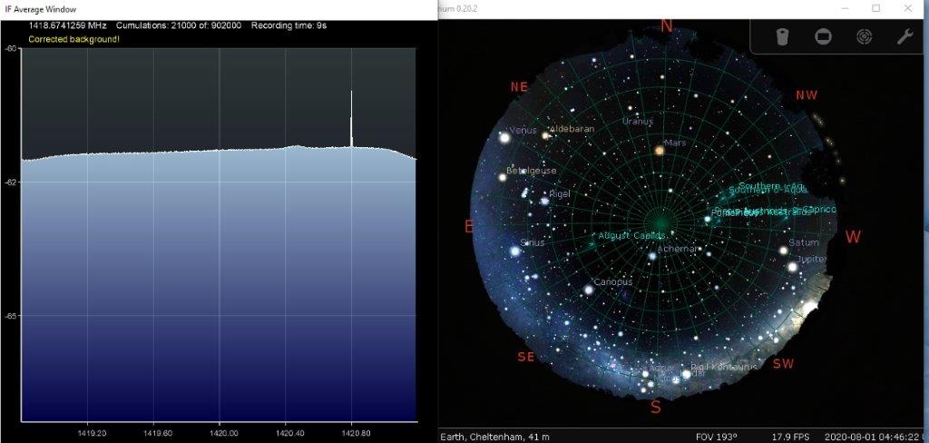
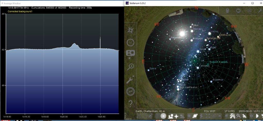
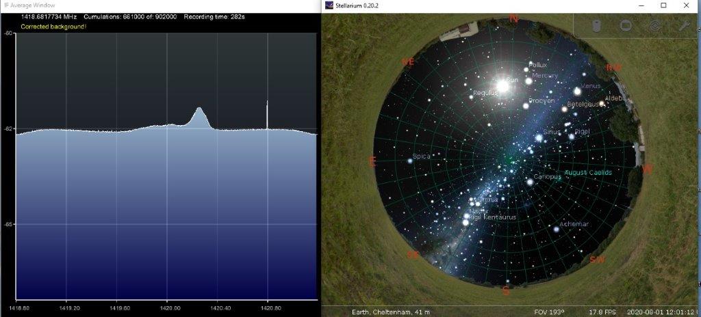
Capture 7 is taken with the Milky Way at the azimuth and the telescope pointing just -20° from the centre of the galaxy. The signal frequency is centred on 1420.35 MHz. Captures 11 and 12 show the signal reducing as the Milky Way drifts out of view. The small observable signal is centred on 1420.4 MHz. The signal builds again over Captures 16 to 17 as the Milky Way again moves towards the azimuth; this time with the telescope pointing away from the centre of the galaxy by approximately -110°. A distinct double peak signal can be seen in Capture 16 and the signal frequencies of this double peak are centred on 1420.26 MHz and 1420.34 MHz.

Figure 9 is a map of the Milky Way showing the direction of the signal source when the Milky Way is at the Azimuth. As noted earlier, Capture 7 is pointing just -20° from the centre of the galaxy bisecting the Sagittarius, Scutum-Centaurus and Norma Arms and then along the length of the Near 3kpc Arm. Captures 16 and 17 are pointing away from the centre of the galaxy by approximately -110° along the end of the Orion Spur and towards the end of the Perseus Arm. The width of the signal source due to the telescope’s 27° 3dB beamwidth is also identified on this map. When pointing away from the Milky Way e.g. Captures 11 and 12, the telescope is pointing at an angle above or below the map, i.e. away from the page. For these captures at an angle from the plane of the galaxy, the detected signal will mainly be from H1 in the local area of the Orion Spur rotating in unison with our motion around the centre of the Milky Way. The detected signal is therefore not Doppler shifted from the free space H1 frequency of 1420.4MHz.
Signals from further away will be Doppler shifted if they are originating in different parts of the Milky Way with a non-zero velocity either away from (red shift) or towards (blue shift) Earth. Captures 7, 16 and 17 all resulted in frequencies below the H1 frequency of 1420.4 MHz indicating a red shift i.e. moving away from the Earth. It is possible to speculate on the reason for these red shifts; however this is done with a lack of precision due to the wide beamwidth of the antenna. In the case of Capture 7, the bulk of detected H1 is located towards the edge of the 27° beamwidth within the central bar of the Milky Way.
Apart from near the centre, matter in spiral galaxies orbits the centre at close to a constant velocity regardless of distance from the centre. This departure from Keplerian Rotation is thought to be due to the distribution of dark matter in these galaxies [6]. In the case of the Milky Way the velocity of the Sun and all other objects in the spiral arms has been determined to be between 200 and 240 km/sec. More recent studies have estimated it to be 238 km/sec [7]. Although our galaxy rotates much like a pinwheel, with the stars in the arms of the galaxy orbiting the centre, the rotation of the inner bar is believed to be cylindrical [8]. Because the bulk of the signal in Capture 7 is due to this central bar, the signal source does not significantly contribute to a velocity towards or away from the telescope. The Doppler shift in Capture 7 is therefore almost entirely due to the Sun’s velocity away from this source as it orbits the centre of the galaxy. Vector analysis shows this to be approximately 48 km/sec resulting in a red shift of 48 kHz, i.e. a signal of 1420.35 MHz compared with an observed centre frequency of 1420.35 MHz, a remarkable agreement!
The Doppler shifts in Captures 16 and 17 are also due to the relative velocities of the Earth and the signal sources, however in these cases both the velocity of the Solar System and the signal sources contribute to the Doppler shift. The velocity component of the Sun away from the signal sources is approximately 227 km/sec whilst the velocity component towards the Sun of the Orion and Perseus Arms are approximately 173 km/sec and 130 km/sec respectively. The nett velocities are therefore 54 km/sec and 97 km/sec resulting in red shifts of 54 kHz and 97 kHz i.e. signals of 1420.35 MHz and 1420.30 MHz. This compares with measured centre frequencies of 1420.34 MHz and 1420.26 MHz i.e. red shifts of 60 kHz and 140 kHz.
With little more than a wheelie bin, aluminium flashing, an olive oil tin and a paper clip (OK, also some electronics and software) it was possible to detect signals from 20 to 30,000 light years away, including from near the centre of the Milky Way. The agreement between recorded data and theoretical calculations was also remarkable. This exercise has expanded my knowledge of our Galaxy and has given me an existentially profound appreciation of our place within the Universe.
References
- Open Source Radio Telescopes Projects http://www.opensourceradiotelescopes.org/projects/
- Implementing a Horn Radio Telescope in HS Physics and Astronomy Digital Signal Processing in Radio Astronomy – a Research Experience for Teachers. John L. Makous, Providence Day School Charlotte, NC https://www.gnuradio.org/grcon/grcon18/presentations/Open_Source_Radio_Telescopes/2-John_Makous-OSRT.pdf
- Radio Telescopes Horn In With GNU Radio by Al Williams; January 2019 https://hackaday.com/2019/01/20/radio-telescopes-horn-in-with-gnu-radio/
- Track the Movement of the Milky Way With This DIY Radio Telescope by David Schneider; IEEE Spectrum, September 2019. https://spectrum.ieee.org/geek-life/hands-on/track-the-movement-of-the-milky-way-with-this-diy-radio-telescope
- Cheap and Easy Hydrogen Line Radio Astronomy with an RTL-SDR, WIFI Parabolic Grid Dish, LNA and SDRSharp; RTL-SDR.COM, January 2020. https://www.rtl-sdr.com/cheap-and-easy-hydrogen-line-radio-astronomy-with-a-rtl-sdr-wifi-parabolic-grid-dish-lna-and-sdrsharp/
- The Rotation Curve of the Milky Way by Dr. Christopher Palma, Senior Lecturer in the Department of Astronomy and Astrophysics, The Pennsylvania State University; Penn State College of Earth and Mineral Sciences John A. Dutton e-Education Institute: Astro 801 Planets, Stars, Galaxies, and The Universe. https://www.e-education.psu.edu/astro801/content/l8_p8.html
- Rotation Curve of the Milky Way and the Dark Matter Density by Yoshiaki Sofue. Institute of Astronomy, Graduate School of Sciences, The University of Tokyo, Mitaka, Tokyo; Galaxies, April 2020. https://arxiv.org/abs/2004.11688
- New Insight into the Bar in the Center of the Milky Way by National Optical Astronomy Observatory, Tucson, Arizona; Astronomy, December, 2011 https://astronomy.com/news/2011/12/new-insight-into-the-bar-in-the-center-of-the-milky-way
Date: 21 May 2020
Team: Space Cadets
Project Stage: Completed
The following post is from Geoff Van Der Wagen’s blog, and has been replicated with permission, as are all images from the Geoff’s blog. Geoff is part of the Space Cadets team and developed a Heliacal Antenna rather than the horn antennas most teams are building. The blog can be found here: https://thenack.com/2020/05/space-antenna/
Space antenna!
Late in 2019 I heard of an upcoming project by SpaceAustralia to home brew your own radio-telescope, with the objective of peering at the Milky Way. Previously only the domain of scientists with very nice radio dishes, the reducing cost of entry has now put it in range of the hobbyist so it seemed like a cool thing to try.
Any given Hydrogen atom floating in space emits a little pulse of radio energy every 10 million years or so, at 1420.4MHz – Wiki. By measuring the strength of the radio wave emissions and the Doppler shift, you can get an idea of the quantity and direction of the Hydrogen.
Space Australia’s recommended build was a pyramidal horn antenna, but in the interests of doing something a little different I thought about a Helical antenna. This should be a little easier to build, and the fancy antenna simulation software I have access to at work suggested it might be possible to use a Helical antenna for this task. The biggest challenge is the Hydrogen Line signal is very weak – so weak that thermal noise from the Earth is much noisier (and an antenna needs to be very directional).
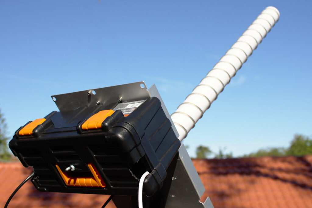
I ended up with a build consisting of an aluminium backplate, a length of 50mm PVC pipe, and some speaker wire wound 20 turns up the outside and hot-glued in place. On the back was a cheap plastic tool box to give some protection to the electronics.
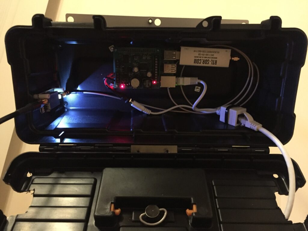
Off the back of the antenna, the preamp is a NooElec SAWBird+ H1, which is 2 LNA’s sandwiching a narrowband filter. This preamp also has a switchable 50 Ohm load, for taking noise calibration measurements. The output is fed to an RTL-SDR.com dongle, with streaming data from the dongle piped through the Raspberry Pi by rtl_tcp and ultimately ending up on my fileserver.
Helical antennas require some impedance matching, which the fancy measuring equipment I have access to at work confirmed was doing the right job. A triangular piece of copper tape converts the 50 ohm feedpoint into the ~120 Ohm characteristic impedance of the antenna.
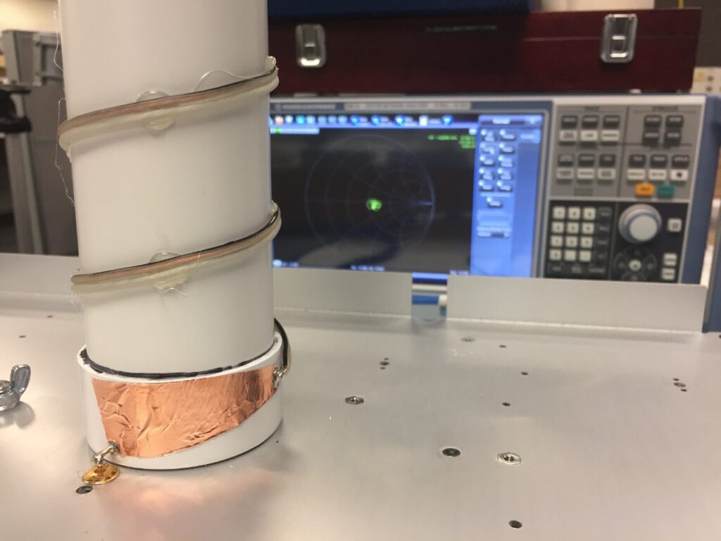
The rest of the measurements looked good too (helicals are broadband impedance-wise, but their pattern degrades quickly away from design frequency):
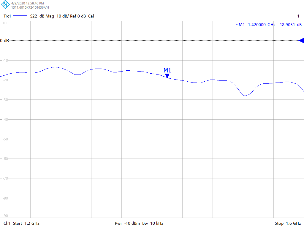
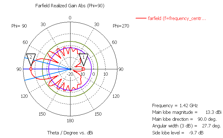
Simulated results suggest a fairly clean pattern. In the below plot, the purple circle is 15dB below the main lobe. 20dB would have guaranteed that a hot Earth wouldn’t degrade my measurements, this design does get there but only directly behind the antenna. I can expect to see some noise degradation with this build unless my antenna points directly upwards.
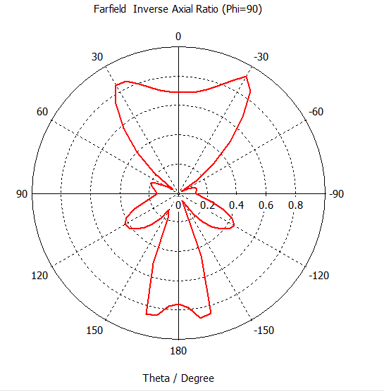
At some point, simulations churned out this interesting-looking plot:
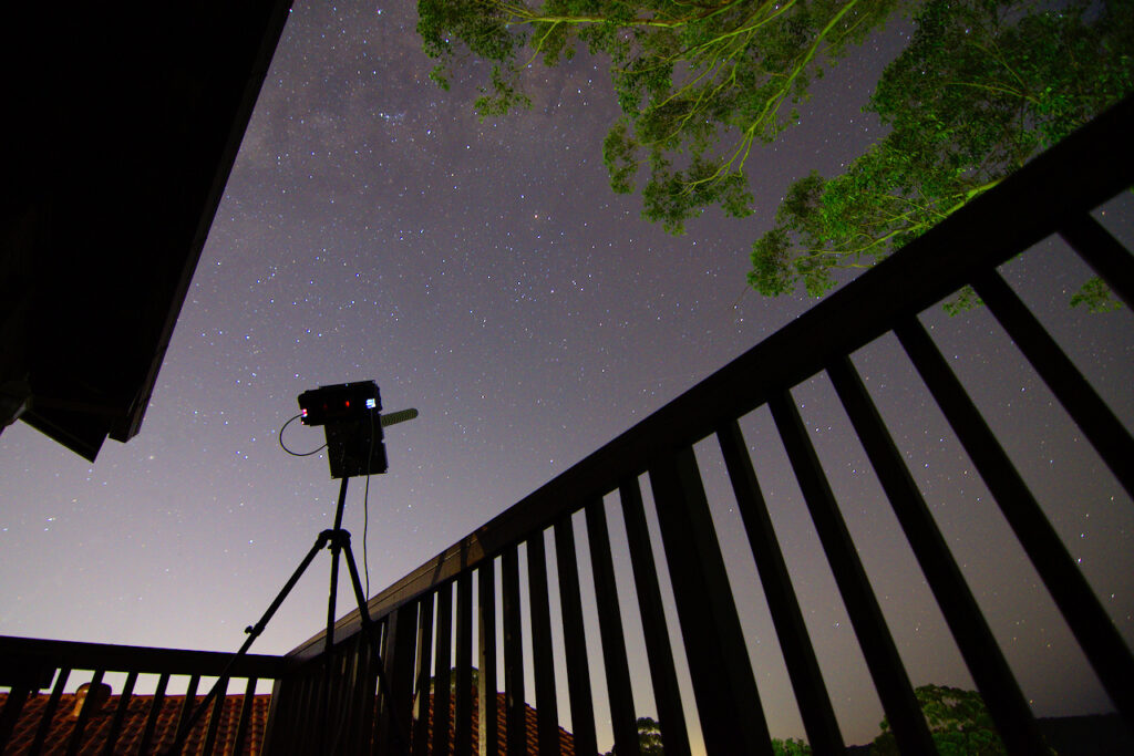
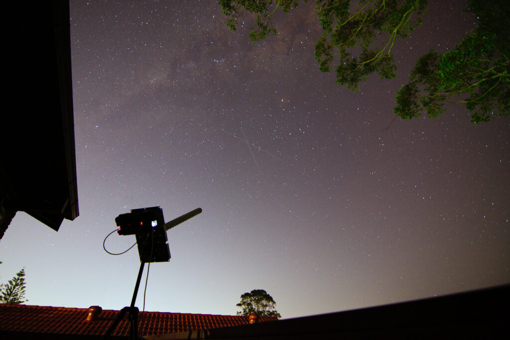
Unfortunately my current location doesn’t have an unobstructed sky view, the best I could do from our balcony was pointing at 45 degrees elevation into a clear patch of sky. Trees, houses, and our own roof conspired to inject noise from the sides but as a system check it was worth trying out. With the fortune of good weather, the antenna stayed out there for 6 full days. In the end this amounted to 1.5TB of raw data.
After much fiddling with the data, there it was! A quite noticeable bump that appears when the Milky Way core (Sagittarius) passes through the antenna beam, and a smaller bump at lower frequency when the opposite direction (Orion) passes through 12 hours later:
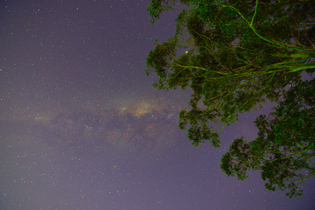
The setup also did look quite photogenic at night:
Date: 7 March
Team: Team Orion
Project Stage: Building Feed-Horns
Today’s workshop strategy was to divide and conquer. And that we did.
We went into today deciding to split the team up to build different components of the telescope, which proved to be very efficient. It’s good to know that we were able to build on all the theory we did in the last session to hit the ground running.
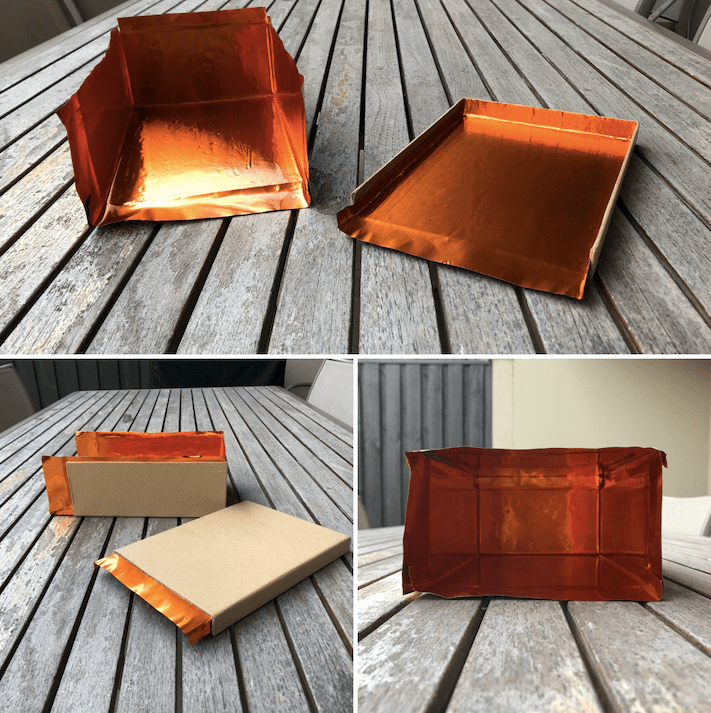
Ginevra worked on building our low-cost waveguide. For this model, we found a cardboard box that is the appropriate size (i.e. has a broad wall of 16.5cm and a shorter wall of 8.5cm) and we are building a faraday cage to contain the signal – by coating the box with mallable copper sheets.
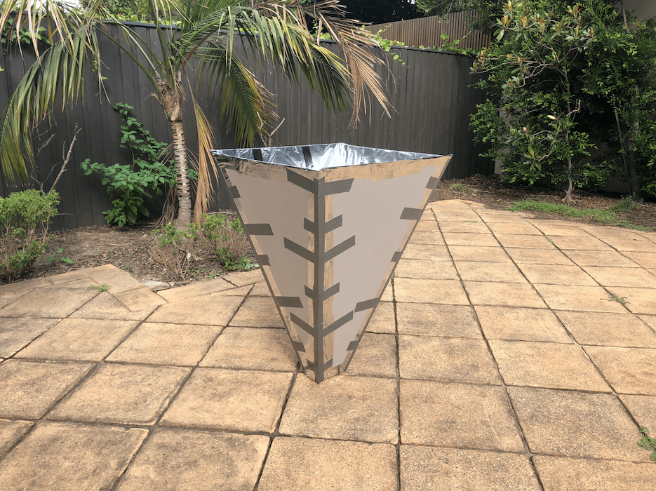
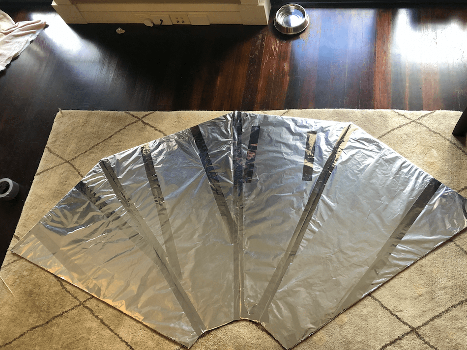
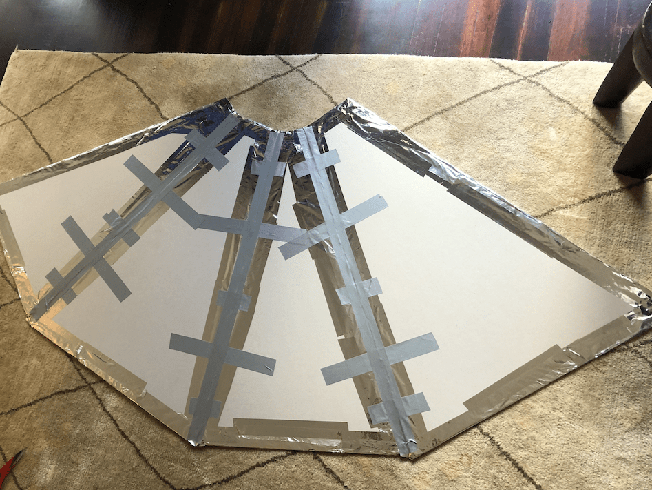
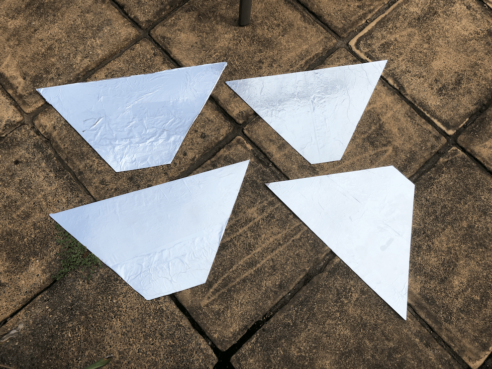
Whilst Ginevera worked on the wave guide, Naif and Rami finalised the prototype short horn, which we had partially constructed during the last lesson – and put together the big 102cm deep feed horn, made from 5mm thick cardboard, aluminium foil and reflective tape (with some gaffa tape for additional support).
To do this, we first cut out the pieces (see our team page for dimensions) and then covered them with AlFoil that was taped down (no gluing this time). Whilst a few bumps appear in the horn, we think it will be ok to guide the 21cm wave down into the antenna regardless. Best to do this part in an open space, as it requires lots of room to move and flip as you tape and adjust. Minimal three people for this part too.

One thing we came across that will be important to future builders is how to structually support the horn (as it is big!) from being floppy. We figured we would build some bamboo shoots (light weight) as a ring around the horn that we slip on and off. We don’t want to permanently fix it because it would make getting through doors challenging!
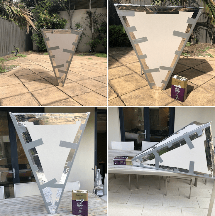
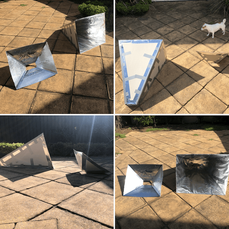
We took both horns (once assembled) outside and stood them up – which gave us a little experimental result … how does the horn deal with the wind. In both cases, it doesn’t! Due to cardboard being rather light and the large surface collecting area/faces, even a slight breeze knocked it about a little. Which told us we need to ensure our mounting in the future is sturdy (and that we should only operate on low-wind days).
When you put the feedhorn by the waveguide (our second model is using an Olive Oil can) the real scale and size of the telescope starts to take shape – and it’s impressive!
Overall, we are really happy with the progress on the horns and are going to commence finalising the olive oil can wave guide and copper box wave guide next week – including connecting our antenna and electronics components – and hopefully acquiring a signal (though, it will not be fine tuned as yet).
Date: 21 February 2020
Team: Team Orion
Project Stage: Electronics Arrive!
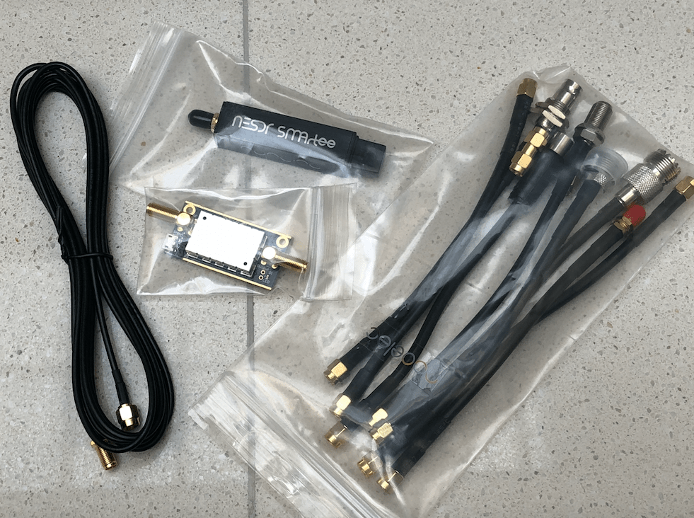
Very excited to see the electronic gear arrive. As our team is testing out a couple of models, we ordered (online) the electronics from two organisations:
1. RTL-SDR.com – this whole package cost us about USD $45 and came with a couple of antennas, chords and the LNA. The receiver still has not arrived as it was stuck in China due to Coronavirus supply chain impacts.
2. Nooelec – this package cost us about USD $110 – but also included a bunch of additional items like exrtra cables and bolts.
We can’t wait to plug it all in!
Date: 15 February 2020
Team: Team Orion
Project Stage: First Construction!
After purchasing our equipment almost a month back, our calendars didn’t align for a quick turnaround of building – but we finally got there.
Our first construction day was both fruitful and frustrating – we thought we had it all mapped out and ready to go in, start cutting things up and then start building.
The reality was, we needed to do some extra thinking and prototyping. In particular, we had to conceptulise the angles and the height of the horns we were building, before we started cutting – so that we would not waste any materials we had purchased.
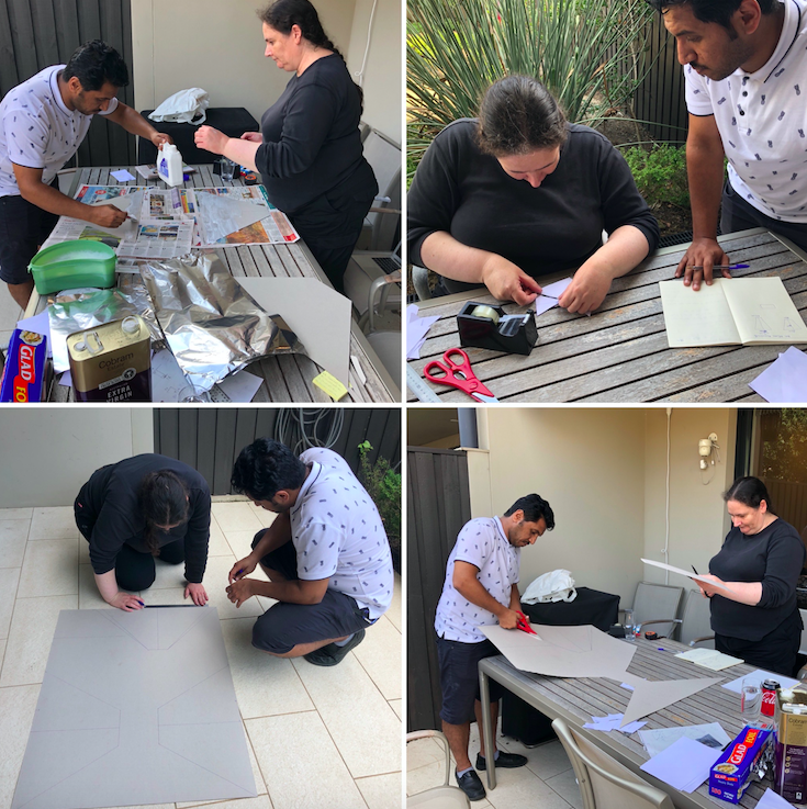
We tried to figure out the best way to cut the sheets of cardboard – so that each sheet could at least produce two faces of the horn. And to do so, we needed to consider the angles within the trapezium that the horn makes (see our team page for these methods).
In the end we only had one horn cut out and the AlFoil glued on, then we had to wait to let it dry. But it wasn’t a loss for us – we needed to go through that thinking process to make sure we understood the dimensions of what we were building properly – to set us up for the next construction session ….
Date: 16 January 2020
Team: Team Orion
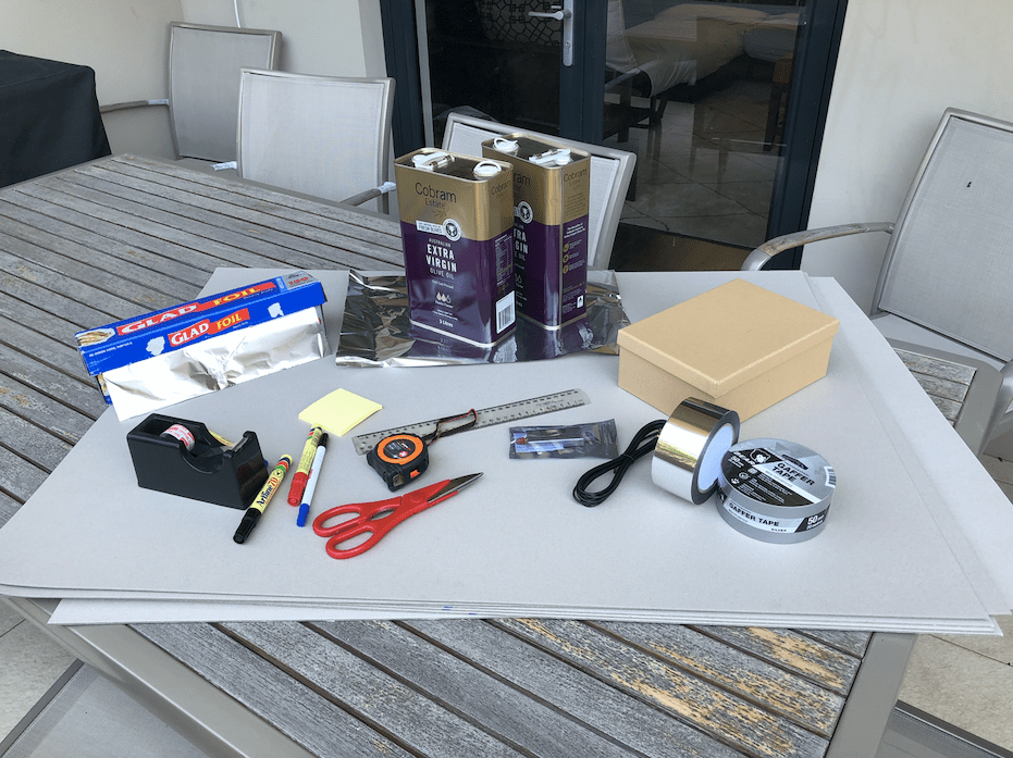
Project Stage: Material Shopping
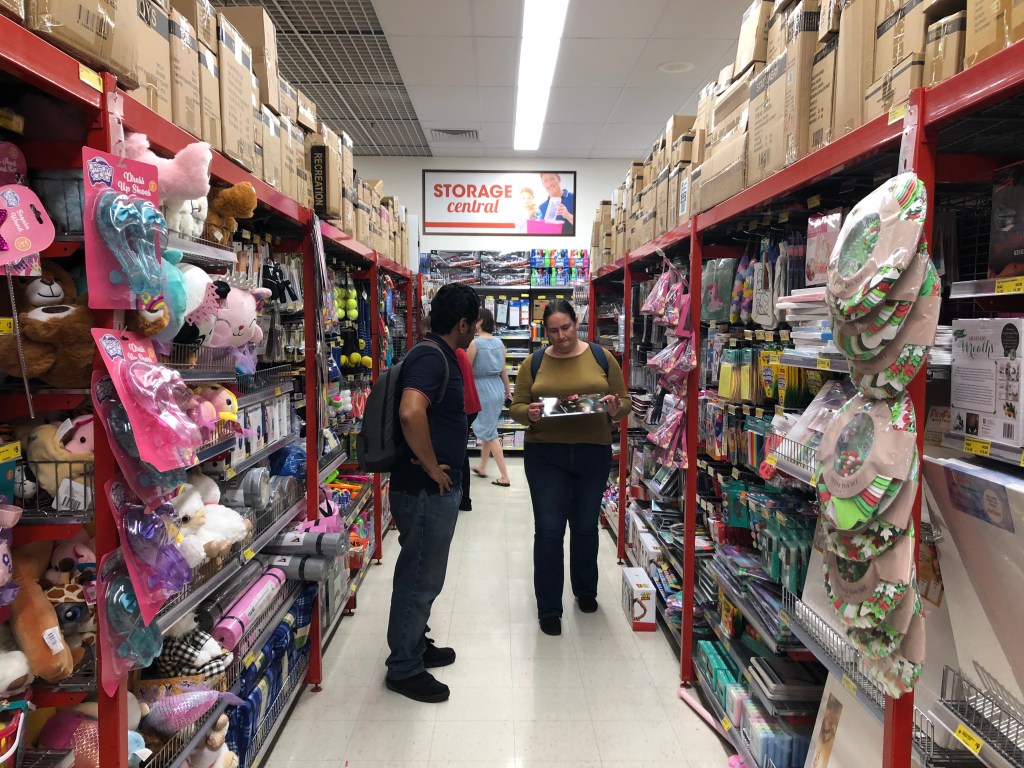
Today was a big day – lots of walking, lots of interesting discussions about our telescopes and lots of new questions that arose from our trip. We set out to visit a amateur radio hobby store in Manly, but before we drove out there – we heard from them that they would not be open today. So we had a morning huddle to change our plans.
Looking at Google Maps, we thankfully were able to work out a solid list of places we wanted to visit for our materials purchases – and it all happened to be in a geographical straight line:
- Reject Shop and Artshop at Broadway Shopping Centre
- Bunnings in Alexandria
- Ikea in Tempe
- Spotlight in Rockdale
As part of our objectives, we want to be able to shocase three different telescope models to future builders – highlighting some easy places they can go and find materials and for what costs (and finally the results these produced).
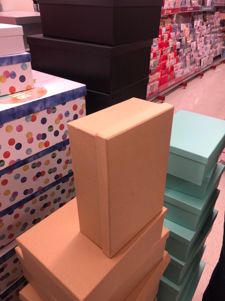
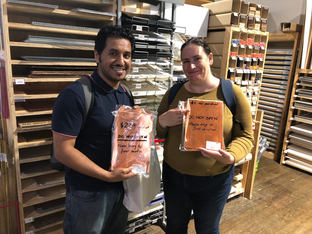
So our first stop was the simple Reject Shop ($2 variety store) where we found a good sized cardboard box for $3. We trotted over to the art shop next to pick up some thin copper sheet for $12. We’re going to merge the two and create the waveguide for our first telescope out of a cheap box coated with copper.
Whilst we were at the art shop, we also looked at some firmer cardboard to constuct our feed horn with for our low-cost model (combined with the copper box). The cost of some decent firm cardboard (it needs to be rigid and have a bit of weight for stability and to keep its shape) is $40 for 4 sheets ($10 each). Getting the cardboard to be a feedhorn is easy – we’re going to cover it in AlFoil found in our kitchens.
Our next stop, we went to Bunnings to consider the build for our mid-range cost telescope model. It’s always so much fun in there – and we spent hours! We looked for Aluminum Flashing material and found out it was called something else – “insulation slverwrap sarkin” or something like that. A 10m roll of this stuff goes for $28.50.
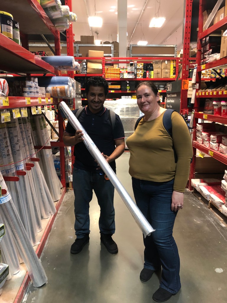
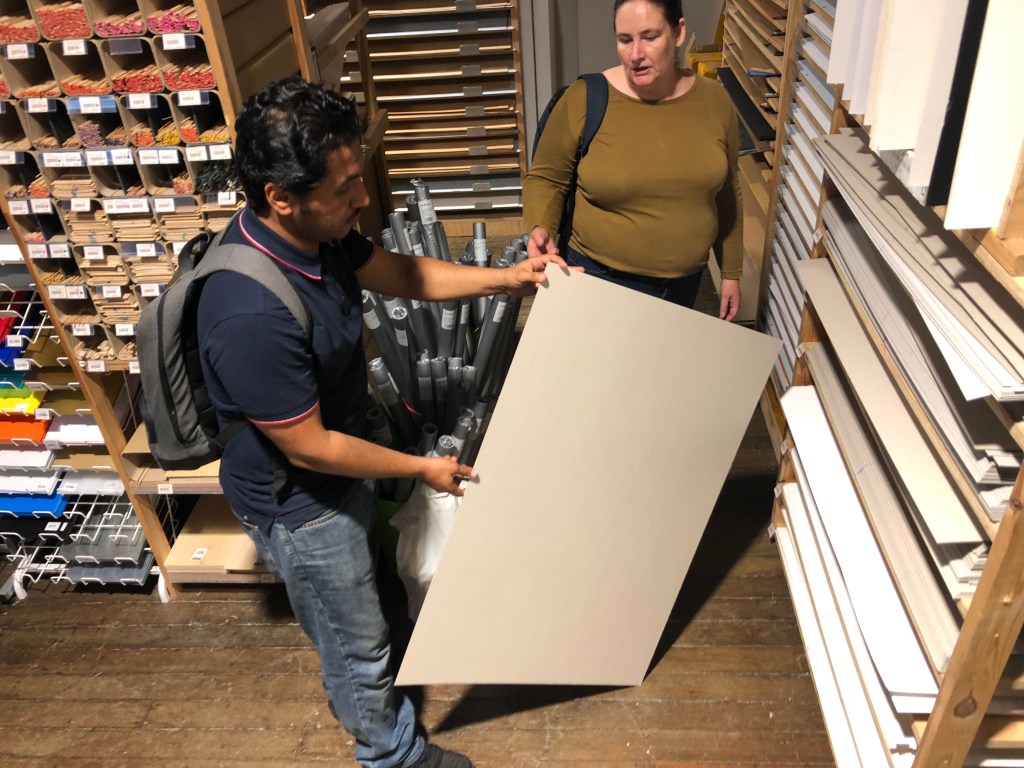
But the Sarkin is really thin, almost paperthin – so we need to give it a backing to build our horn. We looked a range of materials, including:
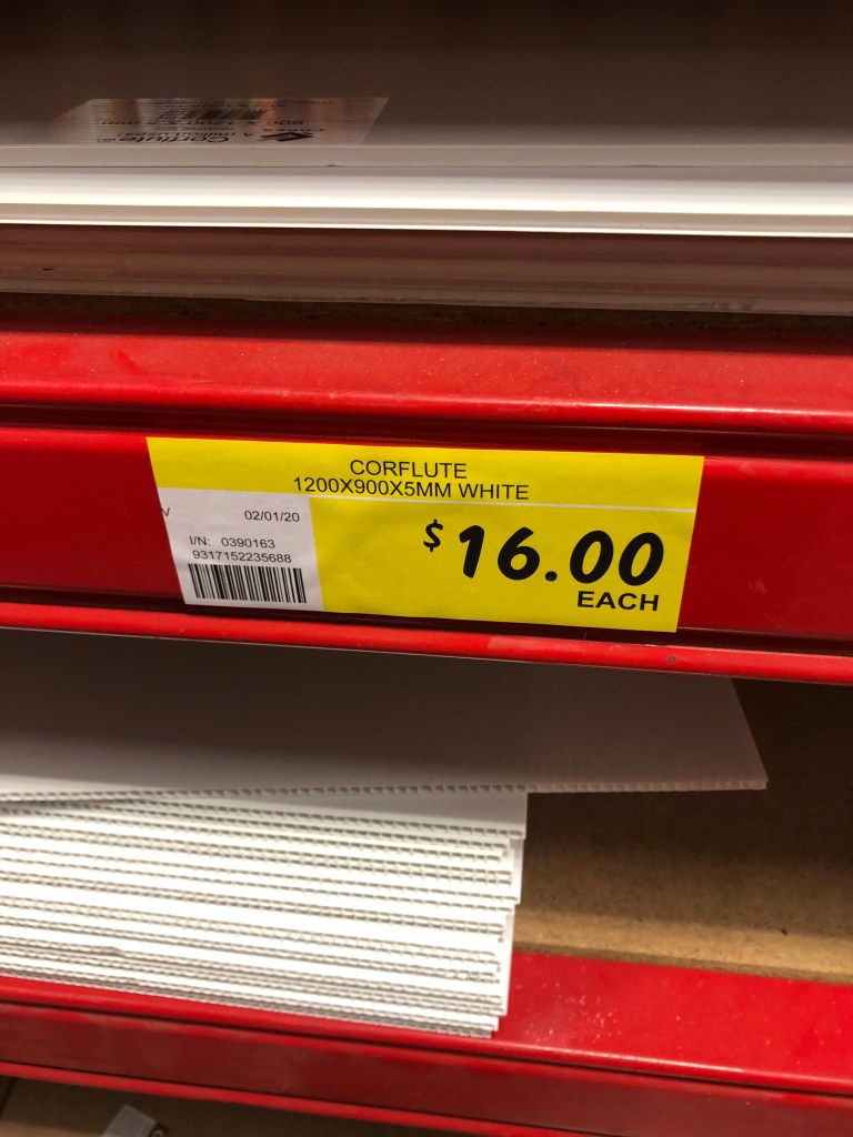
- 5mm thick Corflute – which would cost us about $60 for 4 sheets (1200mm x 900mm) – but we decided this was not too far of the cardboard we bought at the art store (in terms of weight, flexibility etc.) so there was no point of going for this
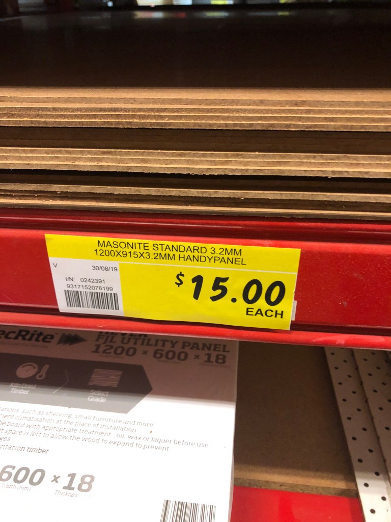
- 3.2mm Masonite – which would cost us about $60 for 4 sheets (1200mm x 900mm) – but when we picked this up, we thought it was rather heavy – and this triggered questions for us about how we would support the horn on top of the waveguide
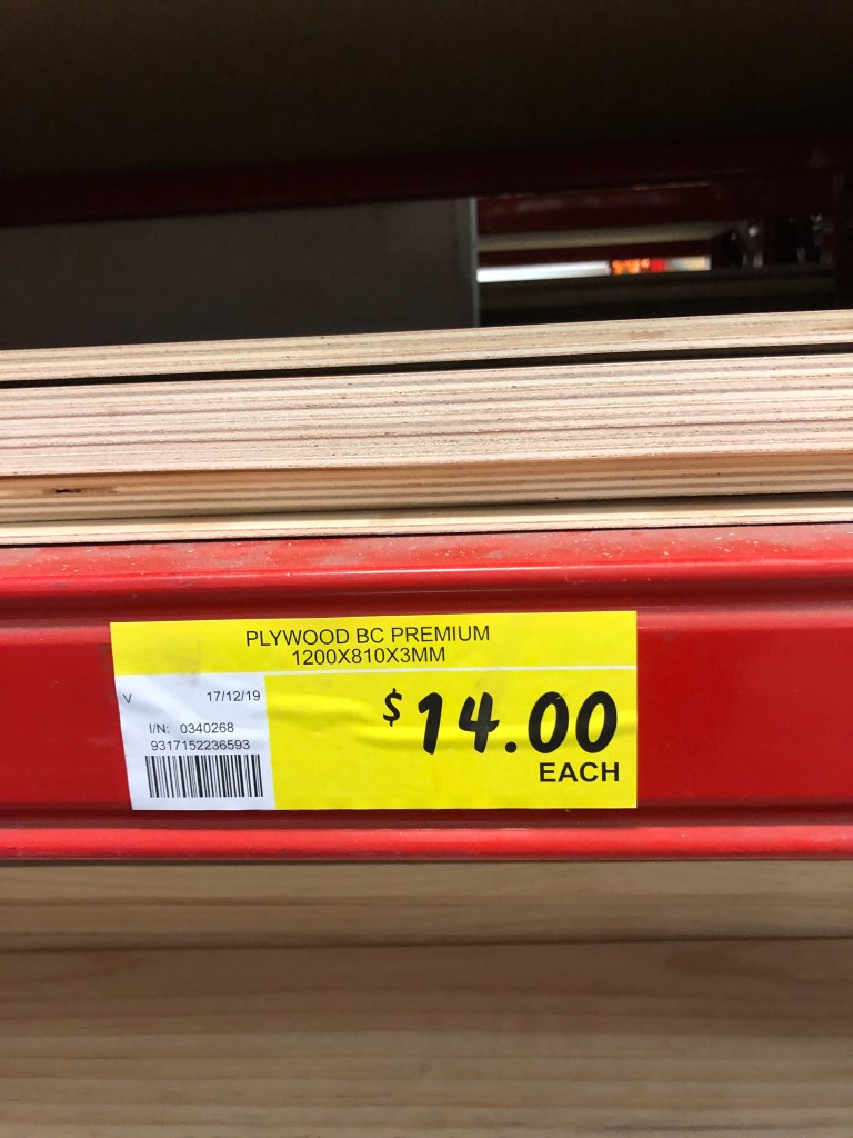
- 3mm Plywood – which would cost us $56 for 4 pieces (1200mm x 810mm) – and this material seemed the best in terms of rigidness vs. weight … it was not too heavy but strong enough to not be wobbly. Yep, this was what we were going to build our mid-range scope with
For our waveguide, we are going to use a 1ltr Olive Oil can from the supermarket, based on what some other folks have said in the Slack Channel. We are still yet to test the strength and dimensions of this.
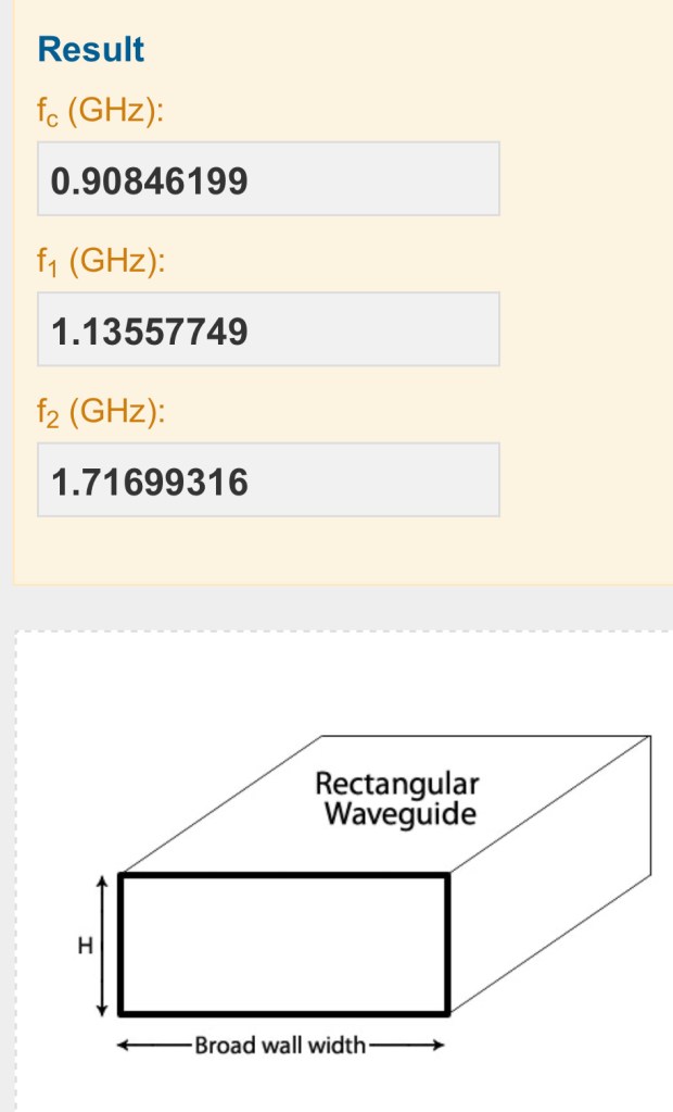
Based on our calcs, we need the broadwall of our waveguide to be between 16cm – 17cm. We used 16.5cm broad wall length on the waveguide calculator and it worked out to give us a frequency range of 1.42GHz with exactly 290 MHz (0.29GHz) on either side. That’s plenty of bandwidth to cover the central frequency peak we’re looking for AND any doppler shift on either side. We’re hoping the Olive Oil can can meet this requirement.
We didn’t make it to Ikea or Spotlight – but we didn’t need to. More shopping on Saturday …. electronics (LNA + receiver) and picking up some odd-ends from Bunnings and the art shop again ….
